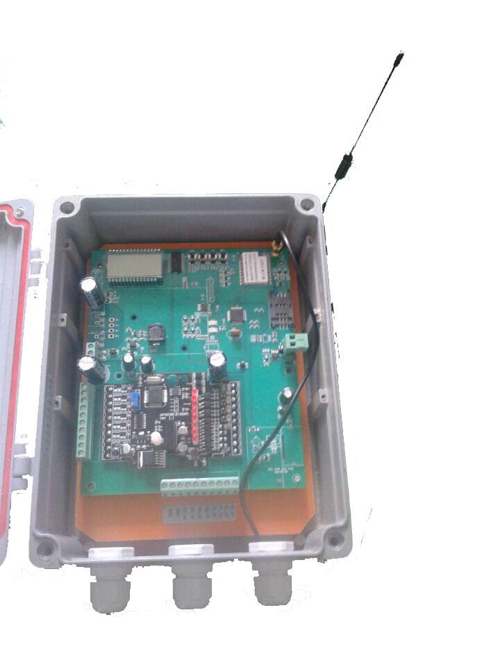
Introduction:
RTU INDUSTRIAL CONTROL COLLECTOR IS m RTU IND y company after years of technical practice and engineering application, in order to meet the market demand and developed a set of wireless GPRS communication and data acquisition as one of the terminal products. This product can collect multi-channel analog quantity, switch quantity, data acquisition speed is fast, high precision. Products to Unicom or mobile GPRS as the communication platform to complete the transmission of data collection, such a communication mode will not be restricted by geography, stability, reliability, low cost advantages. All data parameters can be queried or set through the upper computer software.
Technical specifications:
1. Supply voltage: DC12V;
2. Communication mode: GPRS;
3. Input current: instantaneous maximum value <300mA, average current < 120mA;
4. Rated power: average less than 5W;
5. ARM microcontroller chip with low power consumption;
6. Industrial customized LCD with more display functions;
7. Size: 210*255*92mm;
8. Working environment temperature: -25~+70 degrees Celsius;
9. Storage temperature: -40~+85 degrees Celsius;
10. Relative humidity: 96%.
Functions:
1. The product provides a variety of input and output interface resources;
A. 6 single-ended analog input interfaces, DC 0-20mA/4-20mA, input accuracy is ±0.02mA;
B. 4 active low-level switch input interfaces, the input type can be controlled by software;
C.4 channel pulse output interface, NPN transistor collector open-circuit output, 500mA;
D. Solar power, energy saving and environmental protection; Can also use DC12V regulated power supply;
2. The system uses mobile or Unicom GPRS communication platform, with no geographical restrictions, stability, reliability, low cost advantages, and the data transmission speed is fast, stable signal;
3. Can be timed to save the data, the time interval can be set by the upper computer (in minutes for setting units), can save a long period of historical data, users can query each historical data through the upper computer;
4. Supports UDP and TCP communication.
5. With LCD display and button selection function, the user can select different domain names for network connection through button setting and LCD display;
6. All functions and data of the product can be queried or set through the upper computer software
7. View function: check RTU online status, interference status, etc.
The interface definition:
AVcc external power input positive end
AGnd external power input end
AI_1+ Channel 1 analog input positive end
AI_2+ Channel 2 analog input positive end
AI_3+ Channel 3 analog input positive end
AI_4+ Input positive end of the fourth analog quantity
AI_5+ Channel 5 Analog input positive end
AI_6+ Channel 6 analog input positive end
Gnd Signal ground, connected to the negative end of analog input
Gnd Signal ground, connected to the negative end of analog input
DI_01 Input number 1
DI_02 Input number 2
DI_03 Input number 3
DI_04 Indicates the fourth digit input
DO_01 Route 1 digital output
DO_02 Channel 2 Digital output
DO_03 Channel 3 Digital output
DO_04 Channel 4 Digital output
485A RS485 signal A+
485B RS485 signal B-
Communications specification:
1. Communication parameter description (factory value) : 9600, N, 8,1
Parameters that
9600 baud rate
N(none) Indicates the parity bit
Eight data bits
1. Stop bit
2. Analog input signal acquisition command:
Send: 01 03 00 00 00 06 C5 C8 (example/hexadecimal)
Data Byte Data Description Remarks
01 1 Module address The address range is 01-FE
03 1 Function Code 03- Read register
0000 2 Register address (type 4X) 0000- Analog input start register address
0006 2 Read Length 0006- Read six registers
C5C8 2 CRC Check code CRC check code of all previous data
Receiving: 01 03 0C 07 69 00 00 00 00 00 00 00 00 00 00 00 00 00 00 B6 26 (example/hexadecimal)
Data Byte Data Description Remarks
01 1 Module address The address range is 01-FE
03 1 Function Code 03- Read register
0C 1 Number of bytes 0C- Reads 12 bytes
0769 12 Read Data 0769- Read analog input channel 1 data
0000
0000
0000
0000
0000
0000- Read analog input channel 2 data
0000- Read analog input channel 3 data
0000- Read analog input channel 4 data
0000- Read analog input channel 5 data
0000- Read analog input channel 6 data
B626 2 CRC Check code CRC check code of all preceding data
Analog quantity The current data of input channel 1 is "0769", which is converted into a decimal number of 1897, and then substituted into the calculation formula:
I=(DATA*20)/4095=(1897*20)/4095≈9.26mA, the current DATA of other channels is 0mA
3. Digital input signal acquisition command:
Send: 01 02 00 00 00 04 79 C9 (example/hexadecimal)
Data Byte Data Description Remarks
01 1 Module address The address range is 01-FE
02 1 Function code 02- Read the input bit
0000 2 Input address (1x type) 0000- Start address of the input bit
0004 2 Read input bits Length 0004- Read four input bits
79C9 2 CRC Check code CRC check code for all previous data
Receiving: 01 02 01 05 61 8B (example/hexadecimal)
Data Byte Data Description Remarks
01 1 Module address The address range is 01-FE
02 1 Function code 02- Read the input bit
01 1 Number of bytes 01- Read the length of one byte
05 1 Read Data 05- Read the input bit status
618B 2 CRC Check code CRC check code for all previous data
The read data "05" is converted into a binary number as "0000 1001". The last four digits are valid and correspond to the four digital input signals DI_04-DI_01 from left to right
Is displayed, that is, DI_04 and DI_01 have input, but other channels have no input
4. Digital output signal control command (multiple control) :
Send: 01 0F 00 00 00 04 01 03 7E 97 (example/hexadecimal)
Data Byte Data Description Remarks
01 1 Module address The address range is 01-FE
0F 1 Function code 0F- Write multiple coils
0000 2 Coil address (type 0X) 0000- Coil starting address
0004 2 Write coil length 0004- Write 4 coils
01 1 Write data byte 01- Write one byte of data
03 1 Write data 03- Write the output state of 4 coils
7E97 2 CRC Check code CRC check code of all previous data
Receiving: 01 0F 00 00 00 04 54 08 (example/hexadecimal)
The written data "03" is converted into a binary number "0000 0011". The last four digits are valid. From left to right, they correspond to the four digital output signals DO_04-DO_01
", that is, DO_02 and DO_01 have output, and other channels have no output. After receiving the correct command, the module will make corresponding actions according to the command, and will reply to indicate
Order to send back to the mainframe, indicating successful communication.
5. Digital output signal control command (single control) :
Send: 01 05 00 00 FF 00 8C 3A (example/hexadecimal)
Data Byte Data Description Remarks
01 1 Module address The address range is 01-FE
05 1 Function code 05- Write a single coil
0000 2 Coil address (type 0X) 0000- digital output (DO_01) coil address
0001- Digital output (DO_02) coil address
0002- Address of the digital output (DO_03) coil
0003- Digital output (DO_04) coil address
FF00 2 Write data FF00- coil open, 0000- coil closed
8C3A 2 CRC Check code CRC check code of all previous data
Received: 01 05 00 00 FF 00 8C 3A (example/hexadecimal)
After receiving the correct command, the module makes corresponding actions according to the command, and sends the reply instruction back to the host, indicating that the communication is successful
6. Digital output status collection command:
Send: 01 01 00 00 00 04 3D C9 (example/hexadecimal)
Data Byte Data Description Remarks
01 1 Module address The address range is 01-FE
01 1 Function code 01- Read the coil status
0000 2 Coil address (type 0X) 0000- Coil starting address
0004 2 Read coil length 0004- Read four coil states
3DC9 2 CRC Check code CRC check code of all previous data
Receiver: 01 01 03 E0 50 (example/hexadecimal)
Data Byte Data Description Remarks
01 1 Module address The address range is 01-FE
01 1 Function code 01- Read the coil status
01 1 Number of bytes 01- Read the length of one byte
03 1 Read Data 03- Read coil status
E050 2 CRC Check Code CRC check code of all previous data
The read data "03" is converted into a binary number "0000 0011". The last four digits are valid, which correspond to the four digital output signals DO_04-DO_01 from left to right
Is displayed, that is, DO_02 and DO_01 have output, but other channels have no output.
7. Module address setting command:
Send: 00 06 00 64 00 01 08 04 (example/hexadecimal)
Data Byte Data Description Remarks
00 1 Module address 00- Group address
06 1 Function code 06- Write single register
0064 2 Register address (type 4X) 0064- Change module address
0001 2 Write data to set the new address of the module. The value ranges from 0001 to 00FE
0804 2 CRC Check Code CRC check code of all previous data
Received: 00 06 00 64 00 01 08 04 (example/hexadecimal)
This command sends a command to a module to set the new address of the module to 01. The setting can be saved when power is lost. The default address of the module is 01 when much is needed
When the modules are networked, the address of each module can be set separately. Because the group address is used, only one address can be set in the 485 network
Module, otherwise, the address of all modules in the 485 network will be set to the same address, please use this directive with caution; When the module receives the correct command, the root
Make the corresponding action according to the command, and send the reply instruction back to the host, indicating that the communication is successful.
8. Communication parameter setting command:
Send: 01 06 00 65 00 02 18 14 (example/hexadecimal)
Data Byte Data Description Remarks
01 1 Module address The address range is 01-FE
06 1 Function code 06- Write single register
0065 2 Register address (type 4X) 0065- Modify communication parameters
0002 2 write data 0001- sets communication parameters 4800,N(no check),8,1
0002- sets communication parameters 9600,N(no check),8,1
0003- set communication parameters 19200,N(no check),8,1
0004- set communication parameters 38400,N(no check),8,1
0005- set communication parameters 4800,E(even check),8,1
0006- set communication parameters 9600,E(even check),8,1
0007- set communication parameters 19200,E(parity check),8,1
0008- set communication parameters 38400,E(parity),8,1
1814 2 CRC Check code CRC check code for all preceding data
Receive: 01 06 00 65 00 02 18 14 (example/hexadecimal)
This command means to issue a command to a module, set the module's communication parameters to '9600,N(no check),8,1', the setting can be saved when power is lost; The module
The default communication parameters are '9600,N(no verification),8,1'. After setting the new communication parameters, select the correct communication parameters in the communication Settings and restart the communication terminal
Please use this instruction with caution. Generally, the set baud rate is low, the transmission speed is slow, the transmission stability is high, the set baud rate is high, the transmission speed is fast
Low transmission stability; When the module receives the correct command, it makes corresponding actions according to the command, and sends the reply instruction back to the host, indicating that the communication is successful.
Communication Indicator Description:
After the module is powered on, the communication indicator turns green
The communication indicator blinks during module communication
The module receives the correct command, and the communication indicator turns green
The module receives an incorrect instruction or an instruction other than the module's address, and the communication indicator turns red
Upper computer debugging instructions
This module provides a debugging software to realize the function debugging and parameter setting of the module. Please follow the following steps:
Connect a computer to a module using an RS485 converter
Connect the 12V or 24V external power supply to the module and power it on. To avoid unnecessary damage, check that the positive and negative ends of the power supply are correctly connected before powering on the module
Open the debugging software, select the corresponding module model, and enter the function debugging or parameter setting screen
Sets the correct communication parameters and opens a communication port
Select the appropriate setup, capture, and control options
 客服1
客服1